
Introduction to Deflection in Structural Engineering
Deflection is an important consideration in structural engineering design. Excessive deflection can cause the structure to be unstable or fail under load. Engineers must consider deflection when designing structures to ensure that the deflection is within acceptable limits for the intended use of the structure. Meeting these requirements not only ensures the safety of the structure but also enhances its longevity and functional performance.
It’s also important to note that building codes and standards typically specify a maximum allowable deflection for different types of structures. These limits vary depending on the structure’s purpose and design requirements, ensuring not only safety but also comfort and usability. By keeping calculated deflections within these established limits, engineers help guarantee that a structure will perform reliably under expected loads and maintain its intended function throughout its lifespan.
What is Deflection?
Deflection is the structural response to external forces, resulting in positional changes in the material. It is typically measured as the displacement of a point on the element or as the angle of rotation of a section of the element.
The amount of deflection is expressed as a unit of length—commonly millimeters (mm) in metric systems or inches (in) in imperial units—representing the distance a structural element moves from its original position under load. Since deflection should generally be a small value for most structures, these length units make it easy to quantify and compare.
While deflection can also be described by the angle of rotation, such as in degrees or radians, this is less common in practice. More often, allowable deflection limits are specified using a ratio relative to the span length of the element (such as L/240 or L/360), which provides a unitless measure to help engineers compare performance across beams of different sizes and lengths.
Deflection can occur in any type of structural element, including beams, columns, and plates. Understanding deflection helps engineers determine how much a structure will deform under various load conditions, enabling them to design safer and more reliable buildings and infrastructure.
Factors Affecting Deflection
The amount of deflection in a structural element is influenced by several key factors:
- Load Magnitude and Distribution: The weight and positioning of the load play a significant role in determining the extent of deflection.
- Material Properties: The elasticity of the material, known as the modulus of elasticity, affects how much the material will stretch or compress under load.
- Geometry of the Element: The shape, size, and cross-sectional area of the element impact its stiffness and ability to resist deformation.
While these are the primary considerations, it’s important to note that real-world scenarios often involve additional complexities. Factors such as temperature changes, live loads (like moving vehicles or people), self-weight of the structure, and even long-term effects like creep can all influence deflection. In practice, a structural engineer must account for these variables to ensure accuracy and safety when calculating the deflection of a beam or any structural member.
Understanding these factors is essential for accurately predicting and managing deflection in structural designs.
How is Deflection Calculated?
Engineers use mathematical formulas to calculate deflection in structural elements. The most common formula used to calculate deflection in beams is the Euler-Bernoulli beam equation. This equation relates the deflection of a beam to the applied load, the length of the beam, the moment of inertia of the cross-section, and the modulus of elasticity of the material. The equation is:
This formula allows engineers to predict the deflection and make necessary adjustments to meet design standards and safety requirements.
Common Deflection Scenarios and Formulas
Deflection calculations can vary depending on the configuration and support conditions of the beam. Here are some common scenarios:
Cantilever Beam Deflection
Cantilever beams are fixed at one end and free at the other. They tend to deflect more than other types because they are only supported at one end. The position of the load and the distance from the fixed support significantly influence the amount of deflection—the farther the load from the support, or the longer the beam, the greater the deflection.
Simply Supported Beam Deflection
Simply supported beams are supported at both ends. When subjected to a uniform distributed load (such as self-weight), the maximum deflection typically occurs at the midpoint of the beam, resulting in a smooth, curved deflection shape.
Fixed Beam Deflection
Fixed beams are restrained at both ends, making them stiffer and less prone to deflection compared to cantilever or simply supported beams. The boundary conditions at the supports reduce the maximum deflection for the same loading conditions.
Factors in Deflection Equations
In all cases, the following factors influence deflection calculations:
- Load Magnitude and Type: Point loads, distributed loads, and their locations on the span.
- Material Properties: The modulus of elasticity (stiffness) of the material.
- Geometry: The length of the beam and the moment of inertia of its cross-section.
Building codes and standards typically specify maximum allowable deflections for various structural elements to ensure safety and functionality. Calculated deflections must comply with these limits.
By understanding these scenarios and applying the appropriate formulas, engineers can quickly estimate deflections for different structural configurations and loading conditions. This approach enables efficient design while ensuring structures remain safe and serviceable
Deflection Calculation Example
To illustrate this concept visually, consider the following example. A beam with a length of 3 meters and a cross-sectional area of 0.01 m² is subjected to a load of 1000 N at a distance of 1 meter from the left end. The material is steel with a modulus of elasticity of 200 GPa. Using the Euler-Bernoulli beam equation, we can calculate the deflection at the point where the load is applied:

This means that the deflection at the point where the load is applied is 0.83 millimeters. If the deflection is too large for the intended use of the beam, the engineer may need to increase the cross-sectional area of the beam or choose a material with a higher modulus of elasticity.
Another Common Scenario: Uniform Load on a Simply Supported Beam
For a broader perspective, let’s look at a classic case involving a simply supported beam subjected to a uniform load. Suppose you have a beam with a span of 10 meters, carrying a uniform load of 10,000 N/m. The beam is made from a material with a Young’s modulus of 200 GPa, and its moment of inertia is 0.0015 m⁴.
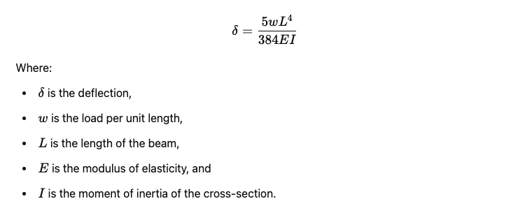
The maximum deflection for this scenario can be determined using the following formula:
[ \delta = \frac{5wL^4}{384EI} ]
Plugging in the values:
- ( w = 10,000 ) N/m
- ( L = 10 ) m
- ( E = 200 ) GPa = ( 200 \times 10^9 ) N/m²
- ( I = 0.0015 ) m⁴
[ \delta = \frac{5 \times 10,000 \times 10^4}{384 \times 200 \times 10^9 \times 0.0015} ] [ \delta = 0.00434 \text{ m } = 4.34 \text{ mm} ]
So, in this case, the maximum deflection at midspan is 4.34 millimeters.
It’s important to note that these examples are simplified for clarity. In real-world engineering, additional factors like temperature changes, live loads, self-weight, and even dynamic forces may need to be considered when evaluating beam deflection. Structural engineers take these complexities into account to ensure safety and reliability in every design.
Implications of Deflection in Structural Design
Deflection is an important consideration in structural engineering design. Excessive deflection can cause the structure to be unstable or fail under load. Engineers must consider deflection when designing structures to ensure that the deflection is within acceptable limits for the intended use of the structure. Meeting these requirements not only ensures the safety of the structure but also enhances its longevity and functional performance.
Conclusion
In conclusion, deflection is an essential concept in structural engineering design. It refers to the amount of deformation that occurs in a structural element when it is subjected to a load. Engineers use mathematical formulas to calculate deflection and must consider it when designing structures to ensure they are safe and stable. By understanding deflection, engineers can create structures that meet the needs of their clients while ensuring safety and reliability.
FAQs
How Is Allowable Deflection Specified?
Allowable deflection in structural design is usually expressed as a ratio of the length of the span to a limiting value, such as L/240 or L/360. This means that the maximum permitted deflection is the span length divided by a specified number, making the limit relative to the size of the structural element. For example, if a beam spans 6 meters and the limit is set at L/360, the allowable deflection would be 6000 mm / 360 ≈ 16.7 mm.
This method allows engineers to set consistent deflection criteria across different structures, regardless of their size. By using a standardized ratio, designers can ensure that deflection remains within acceptable boundaries for both safety and comfort—too much deflection might impact finishes, doors, or simply make a floor feel bouncy.
While deflection can also be measured as a change in angle (in degrees or radians), industry standards almost always rely on linear displacement for practical purposes. Ultimately, specifying allowable deflection in this way ensures designs stay within code requirements and align with best practices for durability and user satisfaction.
Deflection of a Simply Supported Beam Under Uniform Load
To see the principles in action, let’s walk through a practical calculation involving a simply supported beam subjected to a uniform load.
Suppose you have a beam with:
- A span (L) of 10 meters
- Uniform load (w) of 10,000 N/m
- Young’s modulus (E) of 200 GPa
- Moment of inertia (I) of 0.0015 m⁴
For a simply supported beam under a uniform load, the maximum deflection ((\delta_{max})) at midspan is calculated using the following formula:
[ \delta_{max} = \frac{5wL^4}{384EI} ]
Plug in the given values:
- (w = 10,!000, \text{N/m})
- (L = 10, \text{m})
- (E = 200, \text{GPa} = 200 \times 10^9 , \text{N/m}^2)
- (I = 0.0015 , \text{m}^4)
The calculation becomes:
[ \delta_{max} = \frac{5 \times 10,!000 \times (10)^4}{384 \times 200 \times 10^9 \times 0.0015} ]
[ \delta_{max} = \frac{5 \times 10,!000 \times 10,000}{384 \times 200 \times 10^9 \times 0.0015} ]
[ \delta_{max} = \frac{5,000,000,000}{115,200,000,000} ]
[ \delta_{max} \approx 0.00434 , \text{m} = 4.34 , \text{mm} ]
This result indicates a midspan deflection of 4.34 millimeters under the given conditions.
Keep in Mind:
While this scenario uses standard values for clarity, real-world designs must often account for additional variables, such as variable loads, temperature effects, self-weight of the beam, and long-term deformation. Structural engineers incorporate these and other factors to ensure safety and performance under all realistic conditions.
Deflection Shape: Simply Supported vs. Cantilever Beams
To illustrate how deflection varies, let’s compare two common scenarios: the cantilever beam and the simply supported beam. A cantilever beam, fixed at one end and free at the other, tends to bend downward in a long, sweeping arc with the maximum deflection occurring at the free tip.
In contrast, a simply supported beam—resting on supports at both ends—exhibits a very different deflection profile. When subjected to a uniformly distributed load (such as its own weight), the beam gently sags downwards, forming a smooth curve that peaks at the center. The ends, being supported, don’t move vertically at all. This bell-shaped deflection is distinct from the more pronounced curvature of cantilevers, and understanding these patterns is crucial for engineers who need to anticipate how structures will behave under real-world loads.
Influence of Load Position and Beam Length on Cantilever Deflection
When considering cantilever beams—those structural elements anchored firmly at one end with the other end free—both the placement of the load and the overall length of the beam play a significant role in determining the magnitude of deflection.
- Load Position: The farther away a load is applied from the fixed support, the greater the resulting deflection. For example, placing a heavy planter at the tip of a balcony (a classic cantilever scenario) will cause more noticeable sagging than if the same weight is placed closer to where the balcony meets the building.
- Beam Length: Similarly, increasing the overall length of the cantilever leads to increased deflection, even if all other factors—such as load and material—remain constant. This is because a longer “lever arm” gives the applied force more capacity to bend the beam.
In practice, these factors are essential for structural engineers to evaluate, whether designing diving boards, cantilevered roads, or modern architectural overhangs. Appropriate calculations ensure these eye-catching features remain both safe and functional.
Deflection Equations for Cantilever Beams
When analyzing cantilever beams—those fixed at one end and free at the other—it’s essential to use equations tailored for their unique support conditions. Cantilever beams typically exhibit greater deflection than simply supported beams due to their single-point restraint, and understanding how loads influence this behavior is key for effective structural design.
The specific equations for deflection depend on how the load is applied:
- Point Load at the Free End:
The maximum deflection (( \delta_{max} )) at the free end of a cantilever beam subjected to a single point load ( P ) is given by:
[ \delta_{max} = \frac{P L^3}{3 E I} ]
where:- ( P ): Magnitude of the load (N)
- ( L ): Length of the beam (m)
- ( E ): Modulus of elasticity (Pa)
- ( I ): Moment of inertia of the cross-section (m⁴)
- Uniformly Distributed Load (UDL):
For a uniform load ( w ) along the entire span, the maximum deflection at the free end is:
[ \delta_{max} = \frac{w L^4}{8 E I} ]
where ( w ) is the load per unit length (N/m).
Key Points for Design:
- The farther the load is applied from the fixed support (i.e., the longer the cantilever arm), the greater the resulting deflection.
- Structural codes, such as those from the American Institute of Steel Construction (AISC) or Eurocode, specify maximum permissible deflections for different types of structures and uses, to maintain safety and serviceability. Always check current code requirements when evaluating your design.
By applying these formulas, engineers can assess whether a cantilever beam’s deflection falls within acceptable limits, ensuring both the performance and safety of the structure.
Deflection Equations for Fixed Beams
When structural engineers analyze fixed beams—beams that are rigidly secured at both ends—they turn to standard deflection equations to determine how the structure will deform under various loading conditions. Unlike simply supported beams, fixed-end beams distribute and resist loads differently, resulting in lower maximum deflections for the same span and loading.
Here are some commonly used deflection formulas for fixed beams under typical loading scenarios:
- Uniformly Distributed Load (UDL):
- Maximum Deflection at Midspan: [ \delta_{max} = \frac{q L^4}{384 E I} ] Where:
- ( q ) = load per unit length (N/m)
- ( L ) = span length (m)
- ( E ) = modulus of elasticity (Pa)
- ( I ) = moment of inertia (m⁴)
- Maximum Deflection at Midspan: [ \delta_{max} = \frac{q L^4}{384 E I} ] Where:
- Point Load at Center:
- Maximum Deflection at Point of Application: [ \delta_{max} = \frac{P L^3}{192 E I} ] Where:
- ( P ) = point load (N)
- Maximum Deflection at Point of Application: [ \delta_{max} = \frac{P L^3}{192 E I} ] Where:
These equations are derived from classic engineering texts such as Roark’s Formulas for Stress and Strain and are fundamental to beam design. The boundary conditions for fixed ends significantly reduce the allowable movement compared to beams with simply supported ends, an important aspect to keep in mind during the preliminary design phase.
Understanding and applying these fixed beam deflection formulas helps ensure that beams remain within acceptable movement limits, safeguarding both the performance and longevity of structures.
The Importance of Verifying Deflection Calculations
Double-checking hand calculations is essential in structural engineering. Even the best formulas can be impacted by small errors or assumptions, so cross-verifying results—whether with computational tools or alternative calculation methods—helps ensure reliability and safety. This process is especially important because real-world structures are influenced by several variables, such as temperature changes, varying live loads, and the self-weight of materials, which may not be fully captured in a basic example.
By validating your calculations, you reduce the risk of overlooking critical considerations and can catch any mistakes before they impact the design. This careful review process is a key step toward building structures that meet rigorous safety standards and perform as expected under different conditions.